Time Domain Reflectometry (TDR) is a diagnostic technique widely used in electronic failure analysis to evaluate the integrity of conductive paths within devices and assemblies. It is particularly effective for localizing continuity-related defects such as opens, shorts, and impedance discontinuities that are difficult or impossible to detect through visual inspection alone. Because TDR is non-destructive and can be applied early in an investigation, it plays a valuable role in structured fault isolation workflows.
In failure analysis, TDR is commonly applied to packaged integrated circuits (ICs), printed circuit boards (PCBs), cables, connectors, and other conductor-based structures. It is especially useful when failures are intermittent, internal, or buried beneath encapsulation or substrates.
What Is Time Domain Reflectometry (TDR)?
TDR is based on transmission line theory, in which conductors are treated as distributed impedance systems rather than ideal point-to-point connections. In a TDR measurement, a fast electrical pulse is launched into a conductor. As the pulse propagates along the conductive path, it encounters changes in impedance caused by variations in geometry, material properties, or physical damage.
When the pulse encounters an impedance discontinuity, a portion of the signal is reflected back toward the source. The reflected signal carries information about the nature and location of the discontinuity. By measuring the time delay between the transmitted pulse and the reflected response, the distance to the defect can be estimated.
Because the signal propagation velocity is determined by the dielectric environment of the conductor, the measured time delay can be converted into a physical distance. This allows engineers to localize defects without physically accessing the conductor.
How TDR Detects Electrical Discontinuities
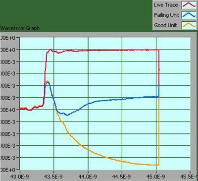
The fundamental strength of TDR lies in its ability to translate electrical reflections into spatial information. Different types of defects produce distinct reflection signatures:
- Open circuits typically produce reflections with one polarity.
- Short circuits generate reflections with the opposite polarity.
- Partial defects, such as cracked traces, voided vias, or localized thinning, produce more subtle impedance changes.
By analyzing reflection amplitude, polarity, and waveform shape, engineers can differentiate between failure modes and assess defect severity. In multilayer PCBs and advanced IC packages, TDR can be used to evaluate internal traces, vias, redistribution layers, bond wires, and other interconnect structures that are otherwise inaccessible.
Resolution depends on several factors, including pulse rise time, system bandwidth, conductor losses, and signal attenuation. Modern high-bandwidth TDR systems are capable of resolving closely spaced features and detecting small impedance variations, making them suitable for today’s dense electronic designs.
Applications in Electronic Failure Analysis
TDR is frequently used during failure analysis and troubleshooting to rapidly narrow the region of interest within a complex device or assembly. Typical applications include:
- Localization of opens or shorts in PCB traces and vias
- Identification of cracked or degraded interconnects
- Evaluation of cable and connector integrity
- Investigation of intermittent continuity failures
- Fault localization in packaged ICs and advanced substrates
Because TDR provides distance-to-defect information, it helps guide subsequent analytical steps. By identifying the approximate failure location early, engineers can minimize unnecessary destructive analysis and preserve valuable samples.
Advantages and Limitations of TDR
One of the primary advantages of TDR is its non-destructive nature. Measurements can often be performed with minimal sample preparation, allowing devices to be analyzed before any material removal occurs. TDR is also relatively fast, enabling efficient screening of multiple samples or test points.
However, TDR does have limitations. Complex geometries, heavy signal attenuation, and highly lossy materials can reduce measurement resolution. In some cases, closely spaced features may produce overlapping reflections that are difficult to interpret. For these reasons, TDR is most effective when used as part of a broader analytical strategy rather than as a standalone technique.
Integrating TDR into a Root Cause Investigation
In practice, TDR is most valuable when integrated into a structured root cause investigation. Results are often correlated with design data, stack-up information, and construction details to map reflections to specific features within a device or assembly.
TDR findings may be used to determine optimal locations for follow-on analysis such as X-ray inspection, cross-sectioning, focused ion beam (FIB) access, or electrical probing. This targeted approach improves efficiency and reduces the risk of missing the true failure site.
At Priority Labs, TDR is commonly used alongside electrical characterization, imaging, and physical analysis methods to build a complete understanding of failure mechanisms. By combining non-destructive fault localization with targeted follow-on techniques, TDR supports clear, defensible engineering conclusions and effective corrective action development.