Time Domain Reflectometry
Time Domain Reflectometry (TDR) is a diagnostic technique used to evaluate the integrity of conductive paths in electronic devices and assemblies. It is commonly applied to packaged integrated circuits (ICs), printed circuit boards (PCBs), cables, connectors, and other conductor-based structures where electrical continuity issues are suspected. TDR is particularly useful in situations where failures are intermittent, internal, or otherwise inaccessible to visual inspection. A general overview of TDR principles and applications is available from Tektronix, a leading test and measurement equipment manufacturer
In a TDR analysis, a fast, controlled electrical pulse is launched into a conductor. As the pulse propagates along the conductive path, it encounters variations in impedance caused by changes in geometry, material properties, or physical damage. When such an impedance discontinuity is encountered, a portion of the signal is reflected back toward the source. By measuring the time required for the reflected signal to return and analyzing its amplitude and polarity, the presence and approximate location of a defect can be determined.
Because the propagation velocity of the signal is known or can be estimated based on the dielectric environment, the time delay between the transmitted and reflected signals can be converted into a physical distance. This allows engineers to localize continuity failures such as opens, shorts, cracked traces, voids, or degraded interconnects without physically accessing the conductor. As a result, TDR provides a powerful non-destructive method for fault localization early in an investigation. Additional background on signal propagation and impedance behavior can be found through educational resources such as Keysight Technologies.
TDR is frequently used during failure analysis, troubleshooting, and quality investigations to rapidly narrow the region of interest within a complex device or assembly. By identifying the approximate location of a defect, TDR helps reduce the scope of subsequent destructive analysis, preserving valuable samples and minimizing unnecessary material removal. This efficiency is especially important when dealing with high-value components, limited sample quantities, or devices requiring multiple analytical techniques.
Advanced Technical Discussion
From a technical perspective, TDR is based on transmission line theory, in which conductors are modeled as distributed impedance networks rather than ideal point-to-point connections. The injected pulse travels along the conductor at a velocity determined by the effective dielectric constant of the surrounding materials. Any change in characteristic impedance along this path produces a reflection whose characteristics depend on the type and severity of the discontinuity.
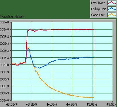
An open circuit generates a reflection with a different polarity and magnitude than a short circuit, while partial defects such as cracked traces, via voids, or localized thinning produce more subtle impedance changes. These signatures can be analyzed to differentiate between failure modes and assess defect severity. In multilayer PCBs and advanced IC packages, TDR can be used to probe traces, vias, redistribution layers, bond wires, and other internal interconnect structures that are otherwise obscured by encapsulation or substrates.
Advanced TDR measurements may involve differential signaling, impedance profiling, and comparison against known-good reference samples to improve diagnostic confidence. Resolution is influenced by factors such as pulse rise time, system bandwidth, conductor losses, and signal attenuation. Modern high-bandwidth TDR instruments are capable of resolving closely spaced features and detecting small impedance variations, making them suitable for today’s dense and complex electronic designs.
In practice, TDR results are often correlated with design data, stack-up information, and physical construction details to map reflections to specific features within a device or assembly. This correlation improves localization accuracy and helps guide subsequent analytical steps. For example, TDR findings may be used to determine the optimal location for cross-sectioning, X-ray imaging, or focused ion beam (FIB) access, ensuring that destructive techniques are applied precisely and efficiently.
At Priority Labs, TDR is commonly integrated into a broader failure analysis and root cause investigation workflow. It is used alongside electrical characterization, imaging, and physical analysis methods to build a complete understanding of failure mechanisms. By combining non-destructive fault localization with targeted follow-on analysis, TDR supports clear, defensible engineering conclusions and practical corrective action development.
Related Services: